


TopologiesEditDiagram of different network topologies. Show
Two basic categories of network topologies exist, physical topologies and logical topologies.[5] The transmission medium layout used to link devices is the physical topology of the network. For conductive or fiber optical mediums, this refers to the layout of cabling, the locations of nodes, and the links between the nodes and the cabling.[1] The physical topology of a network is determined by the capabilities of the network access devices and media, the level of control or fault tolerance desired, and the cost associated with cabling or telecommunication circuits. In contrast, logical topology is the way that the signals act on the network media,[6] or the way that the data passes through the network from one device to the next without regard to the physical interconnection of the devices.[7] A network's logical topology is not necessarily the same as its physical topology. For example, the original twisted pair Ethernet using repeater hubs was a logical bus topology carried on a physical star topology. Token Ring is a logical ring topology, but is wired as a physical star from the media access unit. Physically, AFDX can be a cascaded star topology of multiple dual redundant Ethernet switches; however, the AFDX Virtual links are modeled as time-switched single-transmitter bus connections, thus following the safety model of a single-transmitter bus topology previously used in aircraft. Logical topologies are often closely associated with media access control methods and protocols. Some networks are able to dynamically change their logical topology through configuration changes to their routers and switches. The transmission media (often referred to in the literature as the physical media) used to link devices to form a computer network include electrical cables (Ethernet, HomePNA, power line communication, G.hn), optical fiber (fiber-optic communication), and radio waves (wireless networking). In the OSI model, these are defined at layers 1 and 2 — the physical layer and the data link layer. A widely adopted family of transmission media used in local area network (LAN) technology is collectively known as Ethernet. The media and protocol standards that enable communication between networked devices over Ethernet are defined by IEEE 802.3. Ethernet transmits data over both copper and fiber cables. Wireless LAN standards (e.g. those defined by IEEE 802.11) use radio waves, or others use infrared signals as a transmission medium. Power line communication uses a building's power cabling to transmit data. Wired technologiesEditThe orders of the following wired technologies are, roughly, from slowest to fastest transmission speed.
2007 map showing submarine optical fiber telecommunication cables around the world.
Price is a main factor distinguishing wired- and wireless-technology options in a business. Wireless options command a price premium that can make purchasing wired computers, printers and other devices a financial benefit. Before making the decision to purchase hard-wired technology products, a review of the restrictions and limitations of the selections is necessary. Business and employee needs may override any cost considerations.[12] Wireless technologiesEditPersonal computers are very often connected to networks using wireless links
Exotic technologiesEditThere have been various attempts at transporting data over exotic media: Both cases have a large round-trip delay time, which gives slow two-way communication, but doesn't prevent sending large amounts of information. Network nodes are the points of connection of the transmission medium to transmitters and receivers of the electrical, optical, or radio signals carried in the medium. Nodes may be associated with a computer, but certain types may have only a microcontroller at a node or possibly no programmable device at all. In the simplest of serial arrangements, one RS-232 transmitter can be connected by a pair of wires to one receiver, forming two nodes on one link, or a Point-to-Point topology. Some protocols permit a single node to only either transmit or receive (e.g., ARINC 429). Other protocols have nodes that can both transmit and receive into a single channel (e.g., CAN can have many transceivers connected to a single bus). While the conventional system building blocks of a computer network include network interface controllers (NICs), repeaters, hubs, bridges, switches, routers, modems, gateways, and firewalls, most address network concerns beyond the physical network topology and may be represented as single nodes on a particular physical network topology. Network interfacesEditAn ATM network interface in the form of an accessory card. A lot of network interfaces are built-in. A network interface controller (NIC) is computer hardware that provides a computer with the ability to access the transmission media, and has the ability to process low-level network information. For example, the NIC may have a connector for accepting a cable, or an aerial for wireless transmission and reception, and the associated circuitry. The NIC responds to traffic addressed to a network address for either the NIC or the computer as a whole. In Ethernet networks, each network interface controller has a unique Media Access Control (MAC) address—usually stored in the controller's permanent memory. To avoid address conflicts between network devices, the Institute of Electrical and Electronics Engineers (IEEE) maintains and administers MAC address uniqueness. The size of an Ethernet MAC address is six octets. The three most significant octets are reserved to identify NIC manufacturers. These manufacturers, using only their assigned prefixes, uniquely assign the three least-significant octets of every Ethernet interface they produce. Repeaters and hubsEditA repeater is an electronic device that receives a network signal, cleans it of unnecessary noise and regenerates it. The signal may be reformed or retransmitted at a higher power level, to the other side of an obstruction possibly using a different transmission medium, so that the signal can cover longer distances without degradation. Commercial repeaters have extended RS-232 segments from 15 meters to over a kilometer.[15] In most twisted pair Ethernet configurations, repeaters are required for cable that runs longer than 100 meters. With fiber optics, repeaters can be tens or even hundreds of kilometers apart. Repeaters work within the physical layer of the OSI model, that is, there is no end-to-end change in the physical protocol across the repeater, or repeater pair, even if a different physical layer may be used between the ends of the repeater, or repeater pair. Repeaters require a small amount of time to regenerate the signal. This can cause a propagation delay that affects network performance and may affect proper function. As a result, many network architectures limit the number of repeaters that can be used in a row, e.g., the Ethernet 5-4-3 rule. A repeater with multiple ports is known as hub, an Ethernet hub in Ethernet networks, a USB hub in USB networks.
A network bridge connects and filters traffic between two network segments at the data link layer (layer 2) of the OSI model to form a single network. This breaks the network's collision domain but maintains a unified broadcast domain. Network segmentation breaks down a large, congested network into an aggregation of smaller, more efficient networks. Bridges come in three basic types:
A network switch is a device that forwards and filters OSI layer 2 datagrams (frames) between ports based on the destination MAC address in each frame.[16] A switch is distinct from a hub in that it only forwards the frames to the physical ports involved in the communication rather than all ports connected. It can be thought of as a multi-port bridge.[17] It learns to associate physical ports to MAC addresses by examining the source addresses of received frames. If an unknown destination is targeted, the switch broadcasts to all ports but the source. Switches normally have numerous ports, facilitating a star topology for devices, and cascading additional switches. Multi-layer switches are capable of routing based on layer 3 addressing or additional logical levels. The term switch is often used loosely to include devices such as routers and bridges, as well as devices that may distribute traffic based on load or based on application content (e.g., a Web URL identifier). A typical home or small office router showing the ADSL telephone line and Ethernet network cable connections A router is an internetworking device that forwards packets between networks by processing the routing information included in the packet or datagram (Internet protocol information from layer 3). The routing information is often processed in conjunction with the routing table (or forwarding table). A router uses its routing table to determine where to forward packets. A destination in a routing table can include a "null" interface, also known as the "black hole" interface because data can go into it, however, no further processing is done for said data, i.e. the packets are dropped. Modems (MOdulator-DEModulator) are used to connect network nodes via wire not originally designed for digital network traffic, or for wireless. To do this one or more carrier signals are modulated by the digital signal to produce an analog signal that can be tailored to give the required properties for transmission. Modems are commonly used for telephone lines, using a digital subscriber line technology. FirewallsEditA firewall is a network device for controlling network security and access rules. Firewalls are typically configured to reject access requests from unrecognized sources while allowing actions from recognized ones. The vital role firewalls play in network security grows in parallel with the constant increase in cyber attacks. The study of network topology recognizes eight basic topologies: point-to-point, bus, star, ring or circular, mesh, tree, hybrid, or daisy chain.[18] Point-to-pointEditThe simplest topology with a dedicated link between two endpoints. Easiest to understand, of the variations of point-to-point topology, is a point-to-point communication channel that appears, to the user, to be permanently associated with the two endpoints. A child's tin can telephone is one example of a physical dedicated channel. Using circuit-switching or packet-switching technologies, a point-to-point circuit can be set up dynamically and dropped when no longer needed. Switched point-to-point topologies are the basic model of conventional telephony. The value of a permanent point-to-point network is unimpeded communications between the two endpoints. The value of an on-demand point-to-point connection is proportional to the number of potential pairs of subscribers and has been expressed as Metcalfe's Law. Daisy chainEditDaisy chaining is accomplished by connecting each computer in series to the next. If a message is intended for a computer partway down the line, each system bounces it along in sequence until it reaches the destination. A daisy-chained network can take two basic forms: linear and ring.
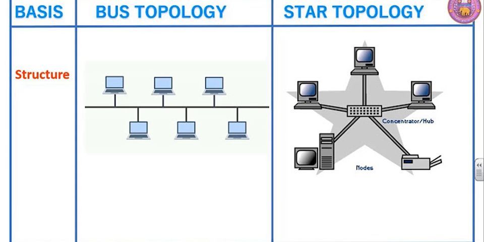
In local area networks using bus topology, each node is connected by interface connectors to a single central cable. This is the 'bus', also referred to as the backbone, or trunk– all data transmission between nodes in the network is transmitted over this common transmission medium and is able to be received by all nodes in the network simultaneously.[1] A signal containing the address of the intended receiving machine travels from a source machine in both directions to all machines connected to the bus until it finds the intended recipient, which then accepts the data. If the machine address does not match the intended address for the data, the data portion of the signal is ignored. Since the bus topology consists of only one wire it is less expensive to implement than other topologies, but the savings are offset by the higher cost of managing the network. Additionally, since the network is dependent on the single cable, it can be the single point of failure of the network. In this topology data being transferred may be accessed by any node. Linear busEditIn a linear bus network, all of the nodes of the network are connected to a common transmission medium which has just two endpoints. When the electrical signal reaches the end of the bus, the signal is reflected back down the line, causing unwanted interference. To prevent this, the two endpoints of the bus are normally terminated with a device called a terminator. Distributed busEditIn a distributed bus network, all of the nodes of the network are connected to a common transmission medium with more than two endpoints, created by adding branches to the main section of the transmission medium– the physical distributed bus topology functions in exactly the same fashion as the physical linear bus topology because all nodes share a common transmission medium. In star topology, every peripheral node (computer workstation or any other peripheral) is connected to a central node called a hub or switch. The hub is the server and the peripherals are the clients. The network does not necessarily have to resemble a star to be classified as a star network, but all of the peripheral nodes on the network must be connected to one central hub. All traffic that traverses the network passes through the central hub, which acts as a signal repeater. The star topology is considered the easiest topology to design and implement. One advantage of the star topology is the simplicity of adding additional nodes. The primary disadvantage of the star topology is that the hub represents a single point of failure. Also, since all peripheral communication must flow through the central hub, the aggregate central bandwidth forms a network bottleneck for large clusters. Extended starEditThe extended star network topology extends a physical star topology by one or more repeaters between the central node and the peripheral (or 'spoke') nodes. The repeaters are used to extend the maximum transmission distance of the physical layer, the point-to-point distance between the central node and the peripheral nodes. Repeaters allow greater transmission distance, further than would be possible using just the transmitting power of the central node. The use of repeaters can also overcome limitations from the standard upon which the physical layer is based. A physical extended star topology in which repeaters are replaced with hubs or switches is a type of hybrid network topology and is referred to as a physical hierarchical star topology, although some texts make no distinction between the two topologies. A physical hierarchical star topology can also be referred as a tier-star topology, this topology differs from a tree topology in the way star networks are connected together. A tier-star topology uses a central node, while a tree topology uses a central bus and can also be referred as a star-bus network. Distributed starEditA distributed star is a network topology that is composed of individual networks that are based upon the physical star topology connected in a linear fashion– i.e., 'daisy-chained'– with no central or top level connection point (e.g., two or more 'stacked' hubs, along with their associated star connected nodes or 'spokes'). A ring topology is a daisy chain in a closed loop. Data travels around the ring in one direction. When one node sends data to another, the data passes through each intermediate node on the ring until it reaches its destination. The intermediate nodes repeat (re transmit) the data to keep the signal strong.[5] Every node is a peer; there is no hierarchical relationship of clients and servers. If one node is unable to re transmit data, it severs communication between the nodes before and after it in the bus. Advantages:
Disadvantages:
The value of fully meshed networks is proportional to the exponent of the number of subscribers, assuming that communicating groups of any two endpoints, up to and including all the endpoints, is approximated by Reed's Law. Fully connected networkEditFully connected mesh topology In a fully connected network, all nodes are interconnected. (In graph theory this is called a complete graph.) The simplest fully connected network is a two-node network. A fully connected network doesn't need to use packet switching or broadcasting. However, since the number of connections grows quadratically with the number of nodes: c=n(n−1)2.{\displaystyle c={\frac {n(n-1)}{2}}.\,} This makes it impractical for large networks. This kind of topology does not trip and affect other nodes in the network. Partially connected networkEditPartially connected mesh topology In a partially connected network, certain nodes are connected to exactly one other node; but some nodes are connected to two or more other nodes with a point-to-point link. This makes it possible to make use of some of the redundancy of mesh topology that is physically fully connected, without the expense and complexity required for a connection between every node in the network. Hybrid topology is also known as hybrid network.[19] Hybrid networks combine two or more topologies in such a way that the resulting network does not exhibit one of the standard topologies (e.g., bus, star, ring, etc.). For example, a tree network (or star-bus network) is a hybrid topology in which star networks are interconnected via bus networks.[20][21] However, a tree network connected to another tree network is still topologically a tree network, not a distinct network type. A hybrid topology is always produced when two different basic network topologies are connected. A star-ring network consists of two or more ring networks connected using a multistation access unit (MAU) as a centralized hub. Snowflake topology is a star network of star networks.[citation needed] Two other hybrid network types are hybrid mesh and hierarchical star.[20] What is network topology and types of network topology? Topology is derived from two Greek words topo and logy, where topo means 'place' and logy means 'study'. In computer networks, a topology is used to explain how a network is physically connected and the logical flow of information in the network. A topology mainly describes how devices are connected and interact with each other using communication links. In computer networks, there are mainly two types of topologies, they are:
Network topology defines the layout, virtual shape, or structure of the network, not only physically but also logically. A network can have one physical topology and multiple logical topologies at the same time. In this blog, we will mainly concentrate on physical topologies. We'll learn about different types of physical topologies, their advantages, and disadvantages. In a computer network, there are mainly six types of physical topology, they are:
Now let us learn these topologies one by one: Bus TopologyBus topology is the simplest kind of topology in which a common bus or channel is used for communication in the network. The bus is connected to various taps and droplines. Taps are the connectors, while droplines are the cables connecting the bus with the computer. In other words, there is only a single transmission line for all nodes. When a sender sends a message, all other computers can hear it, but only the receiver accepts it(verifying the mac address attached with the data frame) and others reject it. Bus technology is mainly suited for small networks like LAN, etc. In this topology, the bus acts as the backbone of the network, which joins every computer and peripherals in the network. Both ends of the shared channel have line terminators. The data is sent only in one direction and as soon as it reaches the end, the terminator removes the data from the communication line(to prevent signal bounce and data flow disruption). In a bus topology, each computer communicates to another computer on the network independently. Every computer can share the network's total bus capabilities. The devices share the responsibility for the flow of data from one point to the other in the network. For Example Ethernet cable, etc. Following are the advantages of Bus topology:
Following are the disadvantages of Bus topology:
Ring TopologyRing topology is a topology in which each computer is connected to exactly two other computers to form the ring. The message passing is unidirectional and circular in nature. This network topology is deterministic in nature, i.e., each computer is given access for transmission at a fixed time interval. All the nodes are connected in a closed-loop. This topology mainly works on a token-based system and the token travels in a loop in one specific direction. In a ring topology, if a token is free then the node can capture the token and attach the data and destination address to the token, and then leaves the token for communication. When this token reaches the destination node, the data is removed by the receiver and the token is made free to carry the next data. For Example, Token Ring, etc. Following are the advantages of Ring topology:
Following are the disadvantages of Ring topology:
Star TopologyStar topology is a computer network topology in which all the nodes are connected to a centralized hub. The hub or switch acts as a middleware between the nodes. Any node requesting for service or providing service, first contact the hub for communication. The central device(hub or switch) has point to point communication link(the dedicated link between the devices which can not be accessed by some other computer) with the devices. The central device then broadcast or unicast the message based on the central device used. The hub broadcasts the message, while the switch unicasts the messages by maintaining a switch table. Broadcasting increases unnecessary data traffic in the network. In a star topology, hub and switch act as a server, and the other connected devices act as clients. Only one input-output port and one cable are required to connect a node to the central device. This topology is better in terms of security because the data does not pass through every node. For Example High-Speed LAN, etc. Following are the advantages of Star topology:
Following are the disadvantages of Star topology:
Mesh TopologyMesh topology is a computer network topology in which nodes are interconnected with each other. In other words, direct communication takes place between the nodes in the network. There are mainly two types of Mesh:
In a fully connected mesh topology, each device has a point to point link with every other device in the network. If there are 'n' devices in the network, then each device has exactly '(n-1)' input-output ports and communication links. These links are simplex links, i.e., the data moves only in one direction. A duplex link(in which data can travel in both the directions simultaneously) can replace two simplex links. If we are using simplex links, then the number of communication links will be 'n(n-1)' for 'n' devices, while it is 'n(n-1)/2' if we are using duplex links in the mesh topology. For Example, the Internet(WAN), etc. Following are the advantages of Mesh topology:
Following are the disadvantages of Mesh topology:
5. Tree Topology:Tree topology is a computer network topology in which all the nodes are directly or indirectly connected to the main bus cable. Tree topology is a combination of Bus and Star topology. In a tree topology, the whole network is divided into segments, which can be easily managed and maintained. There is a main hub and all the other sub-hubs are connected to each other in this topology. Following are the advantages of Tree topology:
Following are the disadvantages of Tree topology:
Hybrid Topology:A Hybrid topology is a computer topology which is a combination of two or more topologies. In practical use, they are the most widely used. In this topology, all topologies are interconnected according to the needs to form a hybrid. All the good features of each topology can be used to make an efficient hybrid topology. Following are the advantages of Hybrid topology:
Following are the disadvantages of Hybrid topology:
Hence, after learning the various computer network topologies, we can conclude that some points need to be considered when selecting a physical topology:
This is all about the topology and its types in a computer network. Hope you learned something new today. That's it for this blog. Do share this blog with your friends to spread the knowledge. Visit our YouTube channel for more content. You can read more blogs from here. Keep Learning :) Team AfterAcademy! Domain 4: Communication and Network Security (Designing and Protecting Network Security)Eric Conrad, ... Joshua Feldman, in CISSP Study Guide (Third Edition), 2016 StarStar topology has become the dominant physical topology for LANs. The star was first popularized by ARCNET, and later adopted by Ethernet. Each node is connected directly to a central device such as a hub or a switch, as shown in Figure 5.17. Figure 5.17. Star Topology Exam WarningRemember that physical and logical topologies are related, but different. A logical ring can run via a physical ring, but there are exceptions. FDDI uses both a logical and physical ring, but Token Ring is a logical ring topology that runs on a physical star, for example. If you see the word “ring” on the exam, check the context to see if it is referring to physical ring, logical ring, or both. Stars feature better fault tolerance: any single local cable cut or NIC failure affects one node only. Since each node is wired back to a central point, more cable is required as opposed to bus (where one cable run connects nodes to each other). This cost disadvantage is usually outweighed by the fault tolerance advantages. View chapterPurchase book Read full chapter URL:https://www.sciencedirect.com/science/article/pii/B9780128024379000059 Types of Network Topology
The arrangement of a network that comprises nodes and connecting lines via sender and receiver is referred to as network topology. The various network topologies are: In which topology do the nodes share the same communication channel?March 9, 2019 Table of Contents
What is Topology?Network topologies describe the methods in which all the elements of a network are mapped. The topology term refers to both the physical and logical layout of a network. In this network topology tutorial, we will explain:
bus topologycommunications Alternate titles: bus network Share Share Share to social media Facebook Twitter URL https://www.britannica.com/technology/bus-topology
Simple bus networks, such as Ethernet, are common for home and small office configurations. The most common ring network is IBM's Token Ring, which employs a “token” that is passed around the network to control which location has sending privileges. Star networks are common in larger commercial networks since a malfunction at any node generally does not disrupt the entire network. Encyclopædia Britannica, Inc. |

Which topology share the same communication channel?
Pos Terkait


Copyright © 2024 idkuu.com Inc.