


Difference between Star topology and Bus topology
Prerequisite – Types of Network Topology Show
1. Star Topology :  2. Bus Topology : Difference between Ring Topology and Bus Topology in Computer Networks
Prerequisite – Types of Network Topology 1. Ring Topology : 2. Bus Topology :
Article Tags : Computer Networks Difference Between GATE CS Practice Tags : Computer Networks Physical or Logical Network TopologiesWith the brief introduction provided above, we simply understand what a basic computer network is all about. A network topology can either be the physical or logical arrangement of devices on a network. These connected devices can be routers, switches, firewalls, network printers, wireless access points, user computers etc (basically anything that can be assigned an IP address). Note that end user devices are also part of the network topology. Logical topology deals with how data is transferred and flows on the network, while physical topology is concerned with the physical layout of the devices on the network and how they are physically connected. Types of Network TopologiesNetwork topology goes beyond logical or physical arrangement of devices. This brings us to the various types of network topologies available today. These topologies are Bus, Star, Ring, Tree, Hybrid and Mesh network topologies. Let us take a closer look at each of these types mentioned. Bus Topology – Advantages and DisadvantagesBus topology has a network arrangement where nodes make use of a single communication line for data transmission. MORE READING: 10 Best Computer Networking Jobs with High Salaries in USA Many networks at the beginning of computer networking era made use of this topology due to easy implementation. Advantages
Disadvantages
Types of TopologyThere are five types of topology in computer networks: 1. Mesh Topology 2. Star Topology 3. Bus Topology 4. Ring Topology 5. Hybrid Topology TopologiesEditDiagram of different network topologies. Two basic categories of network topologies exist, physical topologies and logical topologies.[5] The transmission medium layout used to link devices is the physical topology of the network. For conductive or fiber optical mediums, this refers to the layout of cabling, the locations of nodes, and the links between the nodes and the cabling.[1] The physical topology of a network is determined by the capabilities of the network access devices and media, the level of control or fault tolerance desired, and the cost associated with cabling or telecommunication circuits. In contrast, logical topology is the way that the signals act on the network media,[6] or the way that the data passes through the network from one device to the next without regard to the physical interconnection of the devices.[7] A network's logical topology is not necessarily the same as its physical topology. For example, the original twisted pair Ethernet using repeater hubs was a logical bus topology carried on a physical star topology. Token Ring is a logical ring topology, but is wired as a physical star from the media access unit. Physically, AFDX can be a cascaded star topology of multiple dual redundant Ethernet switches; however, the AFDX Virtual links are modeled as time-switched single-transmitter bus connections, thus following the safety model of a single-transmitter bus topology previously used in aircraft. Logical topologies are often closely associated with media access control methods and protocols. Some networks are able to dynamically change their logical topology through configuration changes to their routers and switches. The transmission media (often referred to in the literature as the physical media) used to link devices to form a computer network include electrical cables (Ethernet, HomePNA, power line communication, G.hn), optical fiber (fiber-optic communication), and radio waves (wireless networking). In the OSI model, these are defined at layers 1 and 2 — the physical layer and the data link layer. A widely adopted family of transmission media used in local area network (LAN) technology is collectively known as Ethernet. The media and protocol standards that enable communication between networked devices over Ethernet are defined by IEEE 802.3. Ethernet transmits data over both copper and fiber cables. Wireless LAN standards (e.g. those defined by IEEE 802.11) use radio waves, or others use infrared signals as a transmission medium. Power line communication uses a building's power cabling to transmit data. Wired technologiesEditThe orders of the following wired technologies are, roughly, from slowest to fastest transmission speed.
2007 map showing submarine optical fiber telecommunication cables around the world.
Price is a main factor distinguishing wired- and wireless-technology options in a business. Wireless options command a price premium that can make purchasing wired computers, printers and other devices a financial benefit. Before making the decision to purchase hard-wired technology products, a review of the restrictions and limitations of the selections is necessary. Business and employee needs may override any cost considerations.[12] Wireless technologiesEditPersonal computers are very often connected to networks using wireless links
Exotic technologiesEditThere have been various attempts at transporting data over exotic media: Both cases have a large round-trip delay time, which gives slow two-way communication, but doesn't prevent sending large amounts of information. Network nodes are the points of connection of the transmission medium to transmitters and receivers of the electrical, optical, or radio signals carried in the medium. Nodes may be associated with a computer, but certain types may have only a microcontroller at a node or possibly no programmable device at all. In the simplest of serial arrangements, one RS-232 transmitter can be connected by a pair of wires to one receiver, forming two nodes on one link, or a Point-to-Point topology. Some protocols permit a single node to only either transmit or receive (e.g., ARINC 429). Other protocols have nodes that can both transmit and receive into a single channel (e.g., CAN can have many transceivers connected to a single bus). While the conventional system building blocks of a computer network include network interface controllers (NICs), repeaters, hubs, bridges, switches, routers, modems, gateways, and firewalls, most address network concerns beyond the physical network topology and may be represented as single nodes on a particular physical network topology. Network interfacesEditAn ATM network interface in the form of an accessory card. A lot of network interfaces are built-in. A network interface controller (NIC) is computer hardware that provides a computer with the ability to access the transmission media, and has the ability to process low-level network information. For example, the NIC may have a connector for accepting a cable, or an aerial for wireless transmission and reception, and the associated circuitry. The NIC responds to traffic addressed to a network address for either the NIC or the computer as a whole. In Ethernet networks, each network interface controller has a unique Media Access Control (MAC) address—usually stored in the controller's permanent memory. To avoid address conflicts between network devices, the Institute of Electrical and Electronics Engineers (IEEE) maintains and administers MAC address uniqueness. The size of an Ethernet MAC address is six octets. The three most significant octets are reserved to identify NIC manufacturers. These manufacturers, using only their assigned prefixes, uniquely assign the three least-significant octets of every Ethernet interface they produce. Repeaters and hubsEditA repeater is an electronic device that receives a network signal, cleans it of unnecessary noise and regenerates it. The signal may be reformed or retransmitted at a higher power level, to the other side of an obstruction possibly using a different transmission medium, so that the signal can cover longer distances without degradation. Commercial repeaters have extended RS-232 segments from 15 meters to over a kilometer.[15] In most twisted pair Ethernet configurations, repeaters are required for cable that runs longer than 100 meters. With fiber optics, repeaters can be tens or even hundreds of kilometers apart. Repeaters work within the physical layer of the OSI model, that is, there is no end-to-end change in the physical protocol across the repeater, or repeater pair, even if a different physical layer may be used between the ends of the repeater, or repeater pair. Repeaters require a small amount of time to regenerate the signal. This can cause a propagation delay that affects network performance and may affect proper function. As a result, many network architectures limit the number of repeaters that can be used in a row, e.g., the Ethernet 5-4-3 rule. A repeater with multiple ports is known as hub, an Ethernet hub in Ethernet networks, a USB hub in USB networks.
A network bridge connects and filters traffic between two network segments at the data link layer (layer 2) of the OSI model to form a single network. This breaks the network's collision domain but maintains a unified broadcast domain. Network segmentation breaks down a large, congested network into an aggregation of smaller, more efficient networks. Bridges come in three basic types:
A network switch is a device that forwards and filters OSI layer 2 datagrams (frames) between ports based on the destination MAC address in each frame.[16] A switch is distinct from a hub in that it only forwards the frames to the physical ports involved in the communication rather than all ports connected. It can be thought of as a multi-port bridge.[17] It learns to associate physical ports to MAC addresses by examining the source addresses of received frames. If an unknown destination is targeted, the switch broadcasts to all ports but the source. Switches normally have numerous ports, facilitating a star topology for devices, and cascading additional switches. Multi-layer switches are capable of routing based on layer 3 addressing or additional logical levels. The term switch is often used loosely to include devices such as routers and bridges, as well as devices that may distribute traffic based on load or based on application content (e.g., a Web URL identifier). A typical home or small office router showing the ADSL telephone line and Ethernet network cable connections A router is an internetworking device that forwards packets between networks by processing the routing information included in the packet or datagram (Internet protocol information from layer 3). The routing information is often processed in conjunction with the routing table (or forwarding table). A router uses its routing table to determine where to forward packets. A destination in a routing table can include a "null" interface, also known as the "black hole" interface because data can go into it, however, no further processing is done for said data, i.e. the packets are dropped. Modems (MOdulator-DEModulator) are used to connect network nodes via wire not originally designed for digital network traffic, or for wireless. To do this one or more carrier signals are modulated by the digital signal to produce an analog signal that can be tailored to give the required properties for transmission. Modems are commonly used for telephone lines, using a digital subscriber line technology. FirewallsEditA firewall is a network device for controlling network security and access rules. Firewalls are typically configured to reject access requests from unrecognized sources while allowing actions from recognized ones. The vital role firewalls play in network security grows in parallel with the constant increase in cyber attacks. The study of network topology recognizes eight basic topologies: point-to-point, bus, star, ring or circular, mesh, tree, hybrid, or daisy chain.[18] Point-to-pointEditThe simplest topology with a dedicated link between two endpoints. Easiest to understand, of the variations of point-to-point topology, is a point-to-point communication channel that appears, to the user, to be permanently associated with the two endpoints. A child's tin can telephone is one example of a physical dedicated channel. Using circuit-switching or packet-switching technologies, a point-to-point circuit can be set up dynamically and dropped when no longer needed. Switched point-to-point topologies are the basic model of conventional telephony. The value of a permanent point-to-point network is unimpeded communications between the two endpoints. The value of an on-demand point-to-point connection is proportional to the number of potential pairs of subscribers and has been expressed as Metcalfe's Law. Daisy chainEditDaisy chaining is accomplished by connecting each computer in series to the next. If a message is intended for a computer partway down the line, each system bounces it along in sequence until it reaches the destination. A daisy-chained network can take two basic forms: linear and ring.
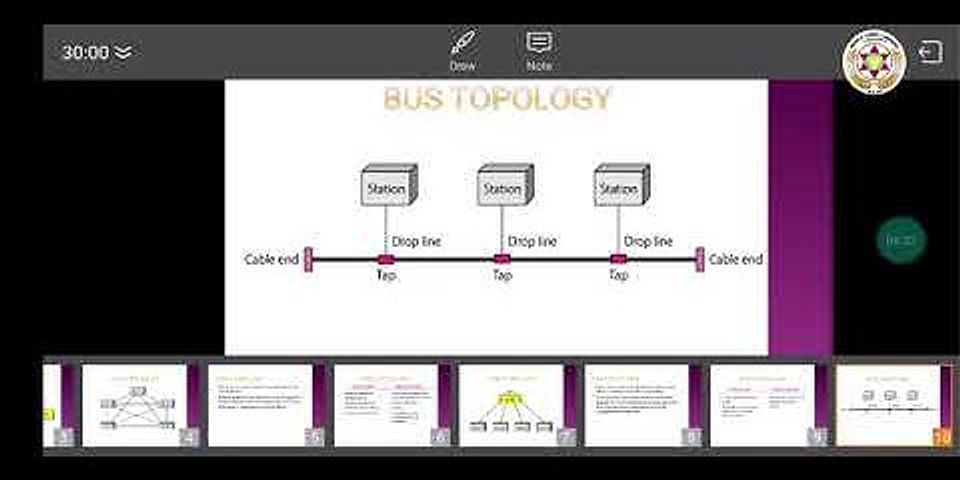
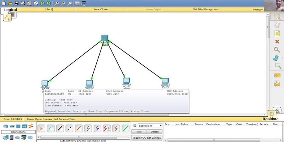
In local area networks using bus topology, each node is connected by interface connectors to a single central cable. This is the 'bus', also referred to as the backbone, or trunk– all data transmission between nodes in the network is transmitted over this common transmission medium and is able to be received by all nodes in the network simultaneously.[1] A signal containing the address of the intended receiving machine travels from a source machine in both directions to all machines connected to the bus until it finds the intended recipient, which then accepts the data. If the machine address does not match the intended address for the data, the data portion of the signal is ignored. Since the bus topology consists of only one wire it is less expensive to implement than other topologies, but the savings are offset by the higher cost of managing the network. Additionally, since the network is dependent on the single cable, it can be the single point of failure of the network. In this topology data being transferred may be accessed by any node. Linear busEditIn a linear bus network, all of the nodes of the network are connected to a common transmission medium which has just two endpoints. When the electrical signal reaches the end of the bus, the signal is reflected back down the line, causing unwanted interference. To prevent this, the two endpoints of the bus are normally terminated with a device called a terminator. Distributed busEditIn a distributed bus network, all of the nodes of the network are connected to a common transmission medium with more than two endpoints, created by adding branches to the main section of the transmission medium– the physical distributed bus topology functions in exactly the same fashion as the physical linear bus topology because all nodes share a common transmission medium. In star topology, every peripheral node (computer workstation or any other peripheral) is connected to a central node called a hub or switch. The hub is the server and the peripherals are the clients. The network does not necessarily have to resemble a star to be classified as a star network, but all of the peripheral nodes on the network must be connected to one central hub. All traffic that traverses the network passes through the central hub, which acts as a signal repeater. The star topology is considered the easiest topology to design and implement. One advantage of the star topology is the simplicity of adding additional nodes. The primary disadvantage of the star topology is that the hub represents a single point of failure. Also, since all peripheral communication must flow through the central hub, the aggregate central bandwidth forms a network bottleneck for large clusters. Extended starEditThe extended star network topology extends a physical star topology by one or more repeaters between the central node and the peripheral (or 'spoke') nodes. The repeaters are used to extend the maximum transmission distance of the physical layer, the point-to-point distance between the central node and the peripheral nodes. Repeaters allow greater transmission distance, further than would be possible using just the transmitting power of the central node. The use of repeaters can also overcome limitations from the standard upon which the physical layer is based. A physical extended star topology in which repeaters are replaced with hubs or switches is a type of hybrid network topology and is referred to as a physical hierarchical star topology, although some texts make no distinction between the two topologies. A physical hierarchical star topology can also be referred as a tier-star topology, this topology differs from a tree topology in the way star networks are connected together. A tier-star topology uses a central node, while a tree topology uses a central bus and can also be referred as a star-bus network. Distributed starEditA distributed star is a network topology that is composed of individual networks that are based upon the physical star topology connected in a linear fashion– i.e., 'daisy-chained'– with no central or top level connection point (e.g., two or more 'stacked' hubs, along with their associated star connected nodes or 'spokes'). A ring topology is a daisy chain in a closed loop. Data travels around the ring in one direction. When one node sends data to another, the data passes through each intermediate node on the ring until it reaches its destination. The intermediate nodes repeat (re transmit) the data to keep the signal strong.[5] Every node is a peer; there is no hierarchical relationship of clients and servers. If one node is unable to re transmit data, it severs communication between the nodes before and after it in the bus. Advantages:
Disadvantages:
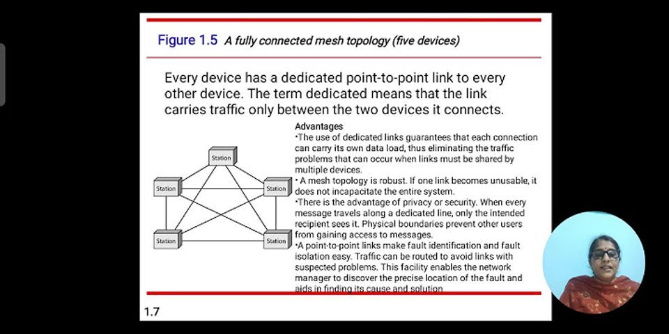
The value of fully meshed networks is proportional to the exponent of the number of subscribers, assuming that communicating groups of any two endpoints, up to and including all the endpoints, is approximated by Reed's Law. Fully connected networkEditFully connected mesh topology In a fully connected network, all nodes are interconnected. (In graph theory this is called a complete graph.) The simplest fully connected network is a two-node network. A fully connected network doesn't need to use packet switching or broadcasting. However, since the number of connections grows quadratically with the number of nodes: c=n(n−1)2.{\displaystyle c={\frac {n(n-1)}{2}}.\,} This makes it impractical for large networks. This kind of topology does not trip and affect other nodes in the network. Partially connected networkEditPartially connected mesh topology In a partially connected network, certain nodes are connected to exactly one other node; but some nodes are connected to two or more other nodes with a point-to-point link. This makes it possible to make use of some of the redundancy of mesh topology that is physically fully connected, without the expense and complexity required for a connection between every node in the network. Hybrid topology is also known as hybrid network.[19] Hybrid networks combine two or more topologies in such a way that the resulting network does not exhibit one of the standard topologies (e.g., bus, star, ring, etc.). For example, a tree network (or star-bus network) is a hybrid topology in which star networks are interconnected via bus networks.[20][21] However, a tree network connected to another tree network is still topologically a tree network, not a distinct network type. A hybrid topology is always produced when two different basic network topologies are connected. A star-ring network consists of two or more ring networks connected using a multistation access unit (MAU) as a centralized hub. Snowflake topology is a star network of star networks.[citation needed] Two other hybrid network types are hybrid mesh and hierarchical star.[20] Overview of Types of Network TopologyNetwork Topology represents a network arrangement consisting of several nodes, i.e. sender and receiver nodes, and the lines connecting them. Types of Network TopologyLet us look at the type of Network Topologies available. Start Your Free Software Development Course Web development, programming languages, Software testing & others 1. Bus TopologyBus topology is the kind of network topology where every node, i.e. every device on the network, is connected to a solo main cable line. Data is transmitted in a single route, from one point to the other. We cannot transmit data in both ways. When this topology has precisely two endpoints, it is known as Linear Bus Topology. It is mostly used for small networks. Benefits of Bus Topology
Drawbacks of Bus Topology
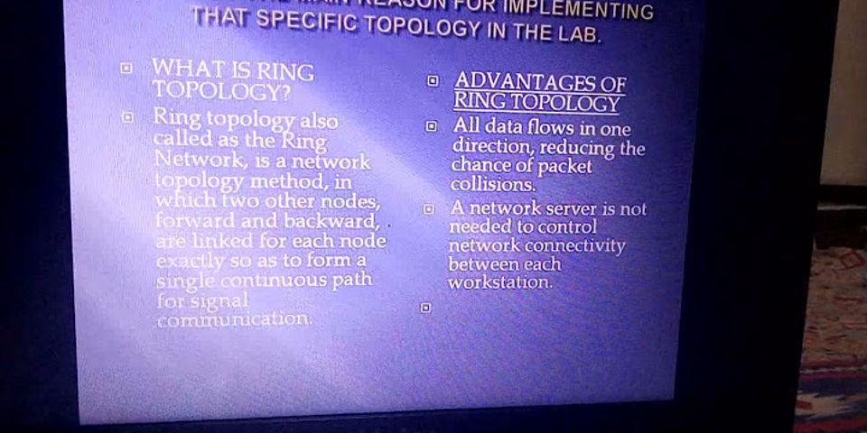
2. Ring TopologyRing Topology is a topology type in which every computer is connected to another computer on each side. The last computer is connected to the first, thus forming a ring shape. This topology allows for each computer to have exactly two neighbouring computers. In this topology, the main computer is known as the monitor station, which is responsible for all the operations. Data transmission amongst devices is done with the help of tokens. For transmitting data, the computer station has to hold the token. The token is released only when the transmission is complete, following which other computer stations can use the token to transmit data. Data transmission is done in a sequential method, i.e. bit by bit. Therefore, data has to route its way through each node in the network to reach the destination node. We use repeaters in a Ring topology to prevent loss of data during transmission. These repeaters are especially helpful when the topology has a vast number of nodes, and the data is to reach the very last node in the network. The data transmission is unidirectional in a Ring topology, but it can be created to be bidirectional by connecting each node with another set of connecting lines. This is known as Dual Ring Topology. Here, two ring networks are created, with the data in each flowing in opposite directions. Popular Course in this category Cyber Security Training (10 Courses, 3 Projects)10 Online Courses | 3 Hands-on Projects | 65+ Hours | Verifiable Certificate of Completion | Lifetime Access Course Price Related Courses CDN Training (2 Courses)OSPF Training Program (2 Courses)Penetration Testing Training Program (2 Courses)Benefits of Ring Topology
Drawbacks of Ring Topology
3. Star TopologyStar Topology is the kind of network topology in which all the nodes are connected via cables to a single node called a hub, which is the central node. The hub can be active or passive in nature. Active hubs contain repeaters, while passive hubs are considered non-intelligent nodes. Each node contains a reserved connection to the central node, which the central node acting as a repeater during data transmission. Benefits of Star Topology
Drawbacks of Star Topology
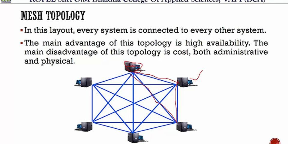
4. Mesh TopologyMesh topology is the kind of topology in which all the nodes are connected with all the other nodes via a network channel. Mesh topology is a point-to-point connection. It hasn(n-1)/2network channels to connectnnodes. Mesh topology has two techniques for transmission of data, i.e. routing and flooding. In the routing technique, the nodes possess a routing logic, like the logic for the shortest distance to the destination node or the logic to avoid routes with broken connections. In the flooding technique, all the network nodes receive the same data. This leaves us no need for routing logic. This technique makes the network robust but results in unwanted load on the network. Benefits of Mesh Topology
Drawbacks of Mesh Topology
5. Tree TopologyTree topology is the topology in which the nodes are connected hierarchically, with all the nodes connected to the topmost node or root node. Hence, it is also known as hierarchical topology. Tree topology has at least three levels of hierarchy. Tree topology is applied in Wide Area Network. It is an extension of Bus topology and Star topology. It is best if the workstations are situated in groups, for easy working and managing. Benefits of Tree Topology
Drawbacks of Tree Topology
6. Hybrid TopologyHybrid Topology is basically a network topology comprising of two or more different types of topologies. It is a reliable and scalable topology, but simultaneously, it is a costly one. It receives the merits and demerits of the topologies used to build it. Benefits of Hybrid Topology
Drawbacks of Hybrid Topology
ConclusionWe have seen the various network topologies available to us, along with their benefits and drawbacks. According to our requirements, it will now be easy for us to choose which network topology can be used. Recommended ArticlesThis has been a guide to Types of Network Topology. Here we discuss 8 network types of topology with their respective benefits and drawbacks. You can also go through our other suggested articles to learn more –
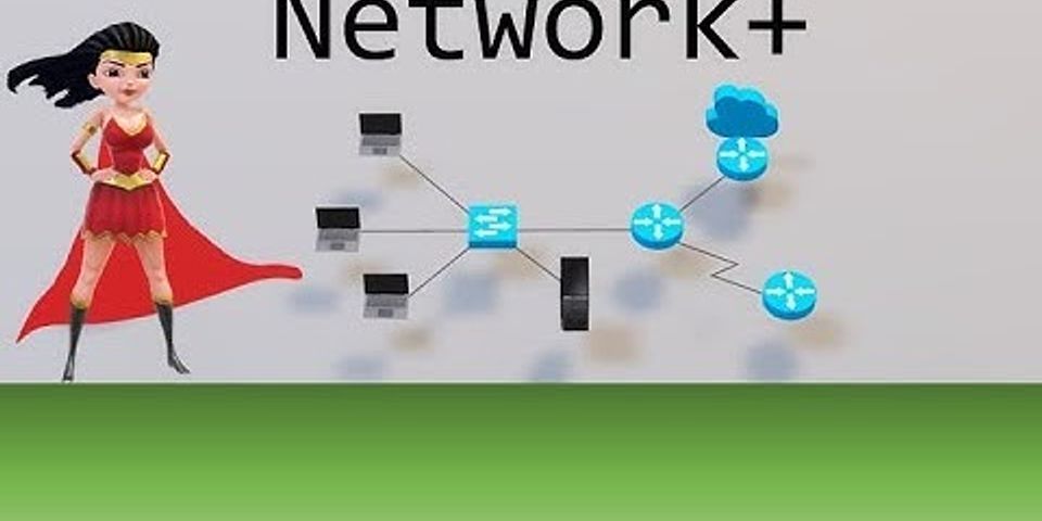
Cyber Security Training (12 Courses, 3 Projects) 10 Online Courses 3 Hands-on Projects 65+ Hours Verifiable Certificate of Completion Lifetime Access Learn More 1 Shares Share Tweet Share Network topologies explained. Find the best topology for home and commercial usesThere are basically eight (8) network topologies studied and recognized across the world: point-to-point topology, bus topology, star topology, ring or circular topology, mesh topology, tree topology, hybrid topology or daisy chain topology. However, here we will only talk those are mainly used. Bus topologyThe first and the simplest form of connection between multiple computers is achieved using bus topology. In case of bus topology, there is a backbone which a large cable, typically coaxial cable that runs through the network and the computers or typically the nodes, which might be a computer, printer, or anything else, are connected to that bus by tapping into the wire. A schematic diagram of bus topology is shown below. As per the above schematic, if node 1 wants to send a document for printing, where the printer is node 5, it will travel through the bus. Now, if some other node wants to send a packet to another node, that will be on the waitlist. In a bus topology, there are two terminators at the end, which serves the purpose of absorbing the signals to prevent bouncing back of the signals, once the task is complete. Bus topology is hardly in use nowadays, as it has a number of disadvantages, which outweighs its advantages in the modern world of technology. Talking about the advantages, it is simple to set up, requires less cabling, and is great for small networks. However, it is really difficult to troubleshoot problems and if the bus goes out of order, the complete network will stop functioning or will be dissected into two, depending upon where the problem is. Bus network is not at all a good idea for big networks, that covers an entire building or so, as the signal will degrade. As the data travels through the bus, any node connected to the network can get hands-on the signal, which creates a privacy problem. Besides that, adding a new node to an existing bus network isn’t a piece of cake either. Even the problems can be solved by replacing taps with Ethernet ports, to some extent, adding new nodes will significantly affect the network speed on a bus topology. Star topologyThis is the most common and the most popular network topology that you can find today. Even the Wi-Fi networks that I have talked about at the beginning of the article is an example of a star topology. In the case of a star topology, there is a central server to which all the nodes are connected and the central server will handle data transaction between the nodes. A schematic diagram of star topology is given below. Let’s consider, node 2 wants to send a packet to node 4. The data transfer will be handled by the central server, without affecting the other nodes on the network. Depending upon the central server and its capabilities, it can even handle multiple data transactions at the same time, like the Multiple MIMO or MU-MIMO in wireless routers. Talking about the advantages of Star topology, it is a child’s play to set up and is very flexible at the same time. As the central server can even be a cheap router or switch, a lot of costs is not involved in setting up a basic star network. You can add extra nodes at any point in time, without making any significant changes in the network. Star topology is one of the best network topologies, as a network will not be affected in any way if a single node goes out of order. However, talking about the disadvantages, if the central server goes out of order the network will stop functioning, and the performance will totally rely on the performance of the server. Just consider your home Wi-Fi router is damaged. In such a situation you can no longer stream videos on your TV, watch online shows and do anything on any of the devices that you have. Ring topologyThe third type of network topology is the ring topology, where each computer is connected to the next one for data transmission to take place till the ends meet. This looks like a ring, and thus, the name. There is no central server or any sort of switch to handle the transmission of data between the nodes. In a ring topology, there is a concept of the token ring which is a 3-byte packet that travels in a single direction around the ring and it can handle data transmission between two nodes at a time. It means if node 1 wants to send a packet to node 4, it has to travel all the way through note 2, followed by note 3 to reach note 4. On the other hand, if a packet is to be sent from node 4 to node 3, it cannot travel backwards. Thus, the packet will travel through node 5, node 1 and node 2 to reach node 3, as per the schematic diagram of ring topology with five computers, that is shown below. If the things are still not clear to you, let me explain the working of ring topology with a different analogy. Just consider, there are five buildings around a playground with a road running through the buildings, where a postman or the token ring can carry a single letter at a time and in a single direction. So, if the building 1 wants to send a letter to building 4, the postman will have to travel all the way through building 2 and building 3 to reach building 4 and it cannot collect any letter in the middle as the postman can carry a single letter at a time. That’s analogous to how a ring topology works. So if the door in one of the buildings is closed, The postman cannot travel at all. Hopefully, you can understand how a ring topology works after this example. Ring topology is kind of similar to peering, which helps us in downloading torrents, where the packets reach a user through multiple nodes on the way. However, peering is much improved and it doesn’t form a ring of computers like ring topology. Talking about the ring topology advantages and disadvantages; it is very simple to set up but is hardly in use nowadays. A complete reconfiguration of the network is necessary to add a new node. Another problem with ring topology is that, if a single computer or node goes out of order, the complete network will stop functioning, just the way, the postman cannot deliver letters, if a door in the building is closed, as per the building analogy. Besides that, if a single computer on the network has a lower processing speed that will affect the performance of the complete network. As data travels in a single direction there is a significant waiting time depending upon the number of computers on the network, processing speed of the computers on the network and the number of requests registered by other computers before you start sending the packet. Security is also a question, as all the packets are transmitted through the nodes. Mesh topologyThe last type of network topology is mesh topology, where all the devices will be directly connected to the other devices on the network. It means, if there are 5 computers on a network, all the five computers will be interconnected with each other. Mesh network is used for achieving the best speeds and reliability. A schematic diagram of mesh topology with 5 computers is shown below. Talking about the mesh topology advantages and disadvantages, even though mesh topology delivers the best performance, a lot of cabling is required to set up a mesh topology, which eventually involves a lot of costs and it’s complicated to set up at the same time. Adding a new node to the network will involve connecting the new node of the computer to all the other devices which makes the setup significantly complicated and is not flexible at all. Computers that will be connected to the mesh network should have in (n-1) network ports to be a part of the mesh network, and {n(n-1)}/2 cables for the network setup, if ‘n’ is a number of nodes on the network. Mesh networks are used only where performance is prioritized over anything else. Tree topologyTrees are there all around us. A tree is basically characterized by a trunk, which is eventually divided into multiple branches. The tree topology works in the same way, where the network has different hierarchies. It is similar to multiple star topologies that are connected with each other through a central server and that server is again connected to others through a server on top of it. The schematic diagram of a tree topology is given below. Tree topology is basically used to cover a big city or multiple cities just the way most internet service providers work. There are advantages and disadvantages of tree topology. Talking about the advantages, if a node or server fails all the nodes and servers under that particular server will stop functioning, and it will not have any effects on the remaining network. Speaking about the disadvantages, a lot of maintenance costs are involved, and as it used mostly for commercial purposes, that’s just a mere disadvantage on pen and paper. A tree topology is the bigger version of a star topology, and thus, in most part, it inherits the advantages and disadvantages of a star topology. It is very easy to understand tree topologies. Just consider there is a headquarters of a company which has offices in different states of the country and each state has multiple offices in the districts and small towns. One more which is important to know… Hybrid topologyThe last type of network topology is hybrid topology, where multiple computers are connected to each other in some kind of topology and it is again connected to another network based on a different topology. So, in a hybrid topology, different computers on small networks can get connected to each other in a particular configuration or topology, and that can even connect to an even bigger network, and it goes on. Here is a small illustration of three small networks, connected in mesh, star, and ring topologies to each other in a star topology, where each network is a node for the ring topology. Talking about the advantages and disadvantages of Hybrid topology, it all depends upon the actual network topologies used to connect the computers. In most cases, hybrid topology is used on a large scale just like tree topology, and it requires high maintenance costs and a lot of cabling depending upon how big the network actually is. Bus, ring, star, and mesh are the fundamental technologies used in computer networks. Tree topology and hybrid topology is built using the four elementary or fundamental topologies available. Talking about which one is the best, star topology is extensively used nowadays, from home to small offices and business. As I have already said, tree topology is implemented by most ISPs out there. Thus, tree topology is the best on a commercial scale and for very big networks and star topology for small networks is undoubtedly the best solution that you can go for. Star topology is very easy to set up, as the central server that I am always talking about is a router in most cases. However, depending upon the requirement of certain companies and also on the number of computers connected, you might even need a full-fledged computer or a dedicated server as the central unit of star topology. But in most cases, a regular or smart router serves as a central hub on star topologies. So that was all about the different network topologies that are available. Hope everything is clear to you now. Do you have some questions to ask? Feel free to comment on the same below. Other Articles:
|

Which of the network topologies are basically bus topologies?
Pos Terkait


Copyright © 2024 idkuu.com Inc.